
Flat Wrap Cable Outer Casing
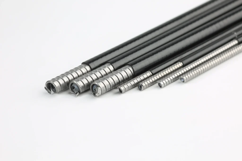
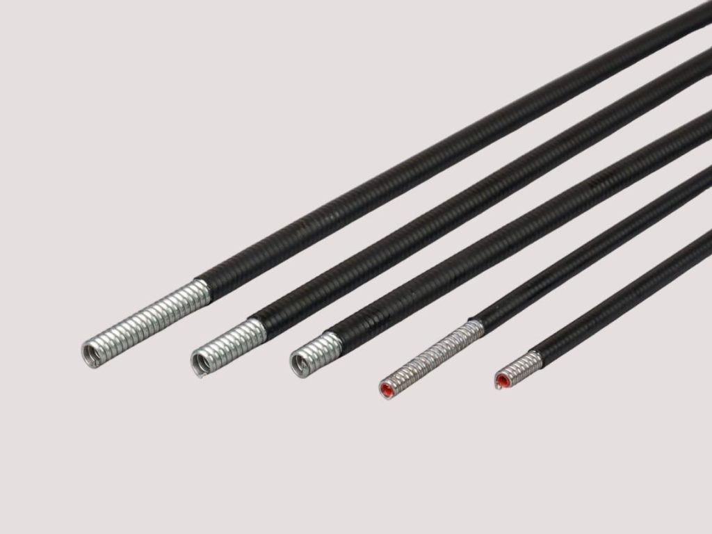
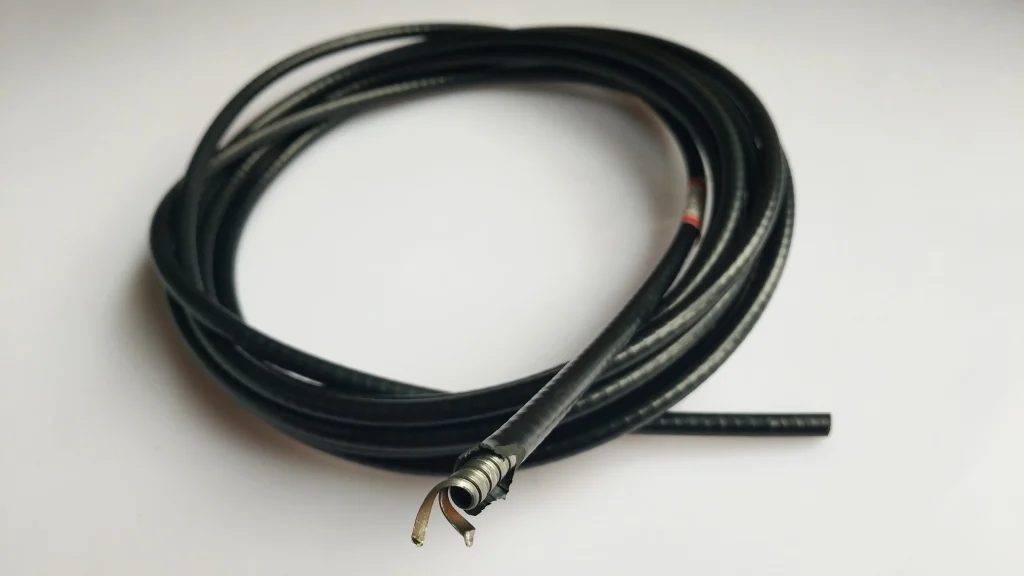
The flat wrap steel cable outer casing serves primarily as a protective conduit for control cables. It is available in two main types: spiral outer casing and twin wire outer casing. An extruded plastic liner may be optionally incorporated inside the conduit, depending on application requirements. We offer fully customized production to meet customer specifications, including material selection, technical requirement, color, dimensions, and packaging.
Technical Parameters
| Specification | Liner Material | Steel Specification | Flattened wire thickness | Coating Material | OD Tolerance | ID |
| φ4 | PE\POM\PTFE\PA\PBT | 0.8-1.0 | 0.48-0.55 | PVC\PP\PA6\PE\TPE\TPEE | ±0.05 | 1.4-1.8 |
| φ5 | PE\POM\PTFE\PA\PBT | 1.05-1.3 | 0.5-0.7 | PVC\PP\PA6\PE\TPE\TPEE | ±0.05 | 1.7-2.0 |
| φ6 | PE\POM\PTFE\PA\PBT | 1.4 | 0.7 | PVC\PP\PA6\PE\TPE\TPEE | ±0.05 | 2.1-3.0 |
| φ7 | PE\POM\PTFE\PA\PBT | 1.6-1.8 | 0.85-1.0 | PVC\PP\PA6\PE\TPE\TPEE | ±0.05 | 3.0-4.0 |
| φ8 | PE\POM\PTFE\PA\PBT | 1.8-2.0 | 1.0-1.25 | PVC\PP\PA6\PE\TPE\TPEE | ±0.05 | 3.3-5.0 |
| φ9 | PE\POM\PTFE\PA\PBT | 2.0-2.1 | 1.1 | PVC\PP\PA6\PE\TPE\TPEE | ±0.075 | 4.0-5.0 |
| φ10 | PE\POM\PTFE\PA\PBT | 2.0-2.2 | 1.25 | PVC\PP\PA6\PE\TPE\TPEE | ±0.075 | 4.0-6.0 |
| φ11 | PE\POM\PTFE\PA\PBT | 2.2-2.4 | 1.1-1.8 | PVC\PP\PA6\PE\TPE\TPEE | ±0.075 | 4.0-6.0 |
| φ12 | PE\POM\PTFE\PA\PBT | 2.2-2.4 | 1.1-1.8 | PVC\PP\PA6\PE\TPE\TPEE | ±0.075 | 4.0-6.0 |
Manufacturing Process
Flat Wrap Cable Outer Casing
Steel Wire Inspection
Liner Tube Inspection
Raw Material (Pellet)
Inspection
Flattening
Tube Winding
Plastic Coating
Coiling & Boxing
Finished Product Inspection
Production requirements
| Name | Model | Remarks |
| Core mold (mandrel) | 4.15 | Before each use, check that the core pin is intact (no notches, deformation, scratches, etc.). After one week of continuous production, check the mold condition with standard plug gauges: 4.15 GO / 4.2 NO‑GO. |
| Die (outer) | 5.1 | Before each use, check the die for scratches, notches, or tears. During production, watch for scratches on the emerging product; if any appear, stop and inspect or replace the die. After one week of continuous production, check with standard plug gauges: 5.1 GO / 5.15 NO‑GO |
| Diameter gauge | / | Setting: Set value must be at least ±0.01 mm narrower than the specified range (set value: 4.93, tolerance ±0.04). |
| Filter screen | 80 mesh / 1 layer | Remarks: Replace the screen after two weeks of continuous production with the same material; also replace when changing materials. During production, if defects larger than 1 mm appear, stop and replace the screen immediately. |
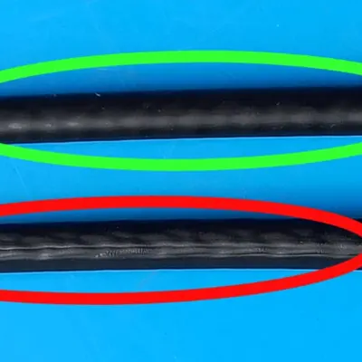
scratch‑like surface marks
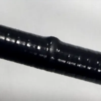
air bubbles
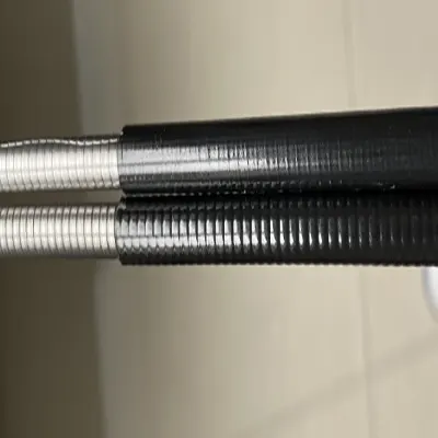
obvious steel wire traces on the surface
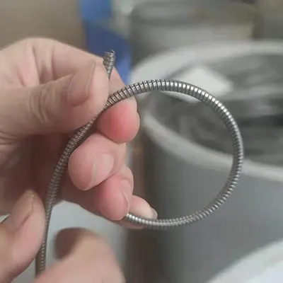
Stiffness/bending
reference diagram
- 1.Pick the raw material of the correct model and grade according to the product information.
- 2.Confirm that all gauges are qualified.
- 3.Verify that the bare tube operation record has the inspector’s release stamp.
- 4.Before starting, perform a point‑by‑point inspection per the equipment checklist; do not start if any abnormality is found.
- 1.Only start the extruder after the set temperatures have been reached for 5–10 minutes, but start within 30 minutes to prevent material degradation.
- 2.The distance from the die to the cooling water must be ≤ 15 cm.
- 3.Visually inspect the product appearance every 20 minutes: within any 1‑meter length, there must be no defect larger than 1 mm in diameter, and fewer than 5 defects smaller than 1 mm (e.g., impurities, bubbles, protrusions). The coating must be free of scratches. Run your hand over the surface to check for foreign matter, bumps, or other anomalies for 2–3 minutes continuously. If any abnormality is found, stop the line immediately, adjust, isolate the affected product, and record the event. If everything is normal, record every 2 hours.
- 4.After an abnormal stop, remove the material from the head.
- 5.The air‑blowing device must be directed toward the water tank; after passing through, the product surface must be free of water stains.
- 6.Perform a first‑piece inspection according to the process requirements. Mass production may begin only after the first piece is approved.
- 7.For each drum of finished coated product, check the outer diameter, inner diameter, and wall thickness difference at the beginning and end of the drum, and also after any abnormal stoppage. Monitor the diameter gauge continuously; if continuous or frequent intermittent alarms occur, adjust immediately, and isolate and label the product.
- 8.The bare tube on the pay‑off stand must have proper tension: it should rotate freely and brake immediately when released. Before entering the core pin, the bare tube passes through a straightener. Adjust the straightener so that the rollers just touch the tube surface; each roller should rotate normally, and the tube must remain centered in the core tip
- 9.Straightness check: take a 1‑meter sample, place it on the straightness gauge at the midpoint, and let the tube hang naturally. The straightness is defined as the left‑right distance S, which must be ≤ 5 cm.
- 10.Stiffness check: take a 540 mm sample, overhang 450 mm, and measure the sag height; it must be ≤ 160 mm. Note: the stiffness test must be performed by rotating the sample 180° and taking the maximum value.
- 11.Shrinkage (inner retraction) check: bend the tube at a radius equal to 10 times its diameter, leaving 3–5 cm at the end, and check for any shrinkage inside.
- 12.For each drum of finished coated product, perform self‑inspection on straightness, stiffness, shrinkage, OD, ID, and wall thickness at the beginning/end and after abnormal stops.
- 13.When changing the die or core pin, wear two layers of gloves (they must be dry). Do not touch the mold directly to avoid burns. Do not drop the mold on the floor. Ensure the internal surfaces are clean of material residue; clean the mold according to the standard cleaning procedure.
- 14.Every 20 minutes, check the bare tube in the basket for back‑twist or tangling; if any is found, handle it immediately.