

Complete plant engineering · worldwide
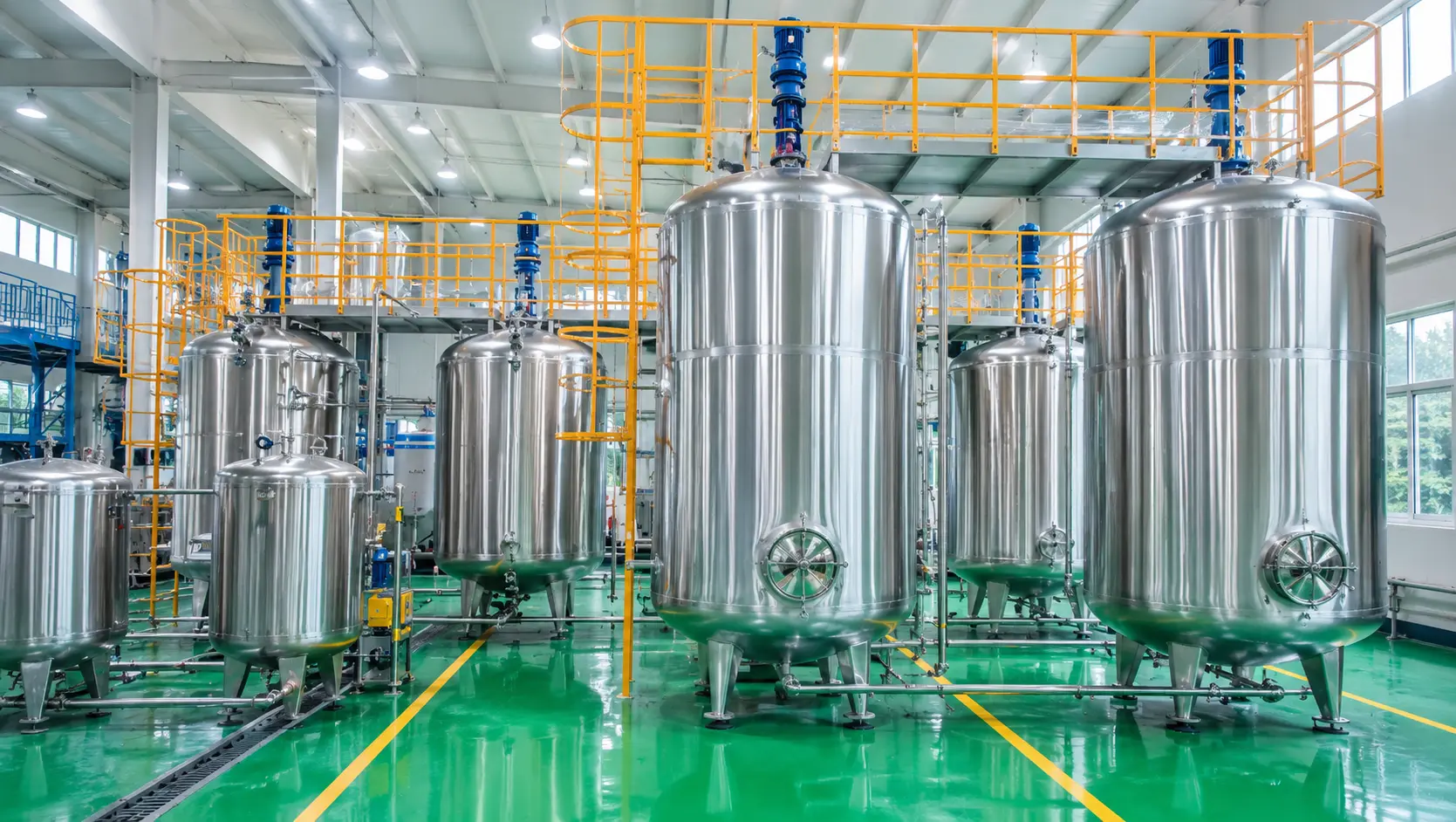
Lubricating Oil Blending Plant
From base-oil and additive reception to recipe-controlled blending, laboratory release, product changeover, filling, packaging and dispatch—engineered as one traceable production system.
Production modes
Batch · circulation · in-line · hybrid
Product flexibility
Automotive and industrial lubricants
Packaging
Small packs · drums · IBC · bulk
Control
PLC/HMI or plant-wide SCADA
01
Project Overview
A lubricating oil blending plant is more than a set of mixing tanks. It is a connected factory that controls raw materials, formulations, product quality, changeover, packaging and production records.
WHAT ENTERS
Base oils and additives
Bulk, drum or IBC receipt with sampling, filtration, identification and storage.
WHAT HAPPENS
Metering and physical blending
No distillation or molecular conversion. Accuracy and uniformity define performance.
WHAT LEAVES
Released finished lubricants
Grade-separated products linked to laboratory results and batch records.
HOW IT SCALES
Modular project engineering
Tank, dosing, blending, filling and automation modules expand with the business.
02
Flexible Formula & Additive Compatibility
The plant is not locked to a VBOLT formula, one additive brand or one additive supplier. Equipment is configured around the client’s approved formulation and the actual properties of each raw material.
Open recipe and additive system
Your formula. Your additive supplier. One flexible plant.
Clients may use their own approved formulations or qualified additive packages from preferred suppliers. VBOLT configures storage, heating, dosing, blending, filtration and cleaning according to component quantity, viscosity, density, recommended handling temperature and mixing requirements.
01 · CLIENT FORMULAS
Import and manage approved recipes
Base oils, additives, addition sequence, temperature and mixing conditions can be stored by product.
02 · SUPPLIER FREEDOM
Use qualified additive packages
The process system can be engineered around packages from the client’s selected suppliers.
03 · FLEXIBLE DOSAGE
Set each ratio by formulation
Major and minor components use the appropriate weighing or flow-metering range.
04 · MATERIAL HANDLING
Adapt equipment to additive properties
High viscosity, heating, pre-mixing, pre-dissolving and cleaning needs are handled project by project.
What this means for the client
Change products or suppliers without replacing the whole plant.
When a new approved recipe or additive package is introduced, VBOLT evaluates the material data and adjusts the recipe, dosing range, handling temperature and changeover procedure.
RECIPE
Version control and production permissions
ADDITIVE PACKAGE
Engine, hydraulic, gear, ATF/CVT and industrial-oil packages
DELIVERY FORM
Bulk liquid, drum, IBC and high-viscosity materials
REQUIRED DATA
SDS, viscosity, density, dosage, temperature and mixing instructions
03
Automotive & Industrial Lubricants the Plant Can Produce
With suitable base oils, qualified additives and an approved formulation, the production line can blend a wide range of automotive and industrial lubricants. SAE and ISO VG identify viscosity grades—not API, ACEA, JASO or OEM approval.
POPULAR PRODUCT GRADES
Automotive Lubricants
Passenger Car Engine Oil
0W-16 · 0W-20 · 0W-30 · 0W-40 · 5W-20 · 5W-30 · 5W-40 · 10W-30 · 10W-40 · 20W-50
Passenger Car Engine Oil
5W-30 · 10W-30 · 10W-40 · 15W-40 · 20W-50 · SAE 30 · SAE 40 · SAE 50
Motorcycle Engine Oil
0W-30 · 10W-40 · 10W-50 · 15W-40 · 15W-50 · 20W-40 · 20W-50
Passenger Car Engine Oil
75W-85 · 75W-90 · 75W-140 · 80W-90 · 85W-140
Transmission & Tractor Fluids
ATF · CVT Fluid · DCT Fluid · MTF · UTTO · STOU
Industrial Lubricants
Hydraulic Oil
ISO VG 22 · ISO VG 32 · ISO VG 46 · ISO VG 68 · ISO VG 100
Industrial Gear Oil
ISO VG 100 · 150 · 220 · 320 · 460 · 680
Compressor Oil
ISO VG 32 · 46 · 68 · 100 · 150
Turbine & Circulating Oil
ISO VG 32 · 46 · 68 · 100 · 150 · 220
Other Industrial Oils
Heat transfer · refrigeration · spindle · chain · quenching · rust preventive · metalworking · marine oils
04
Complete Lubricating Oil Production Process
From raw-material storage to finished-lubricant filling—engineered for formulation accuracy, batch consistency, quality release and flexible dispatch.
01
Raw Material Storage
Base oils and additives stored safely.

02
Recipe & Metering
Accurate metering of base oils and additives


03
Additive Preparation
Additives pre-mixed or pre-dissolved as required.
04
Lubricant Blending
Components blended to exact specification.
05
Testing & Release
Quality testing and batch release.
06
Filling & Dispatch
Finished products packed and shipped worldwide.

1-5L 
10-20L 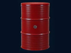
200L Drum 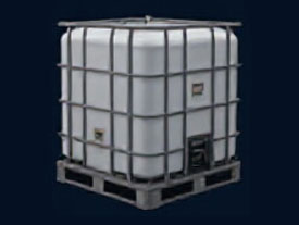
IBC 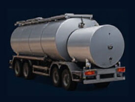
Bulk Tanker
01Raw Material Storage
PURPOSE
Receive, identify, test and store base oils and additives without cross-contamination.
MAIN EQUIPMENT
Unloading connections · transfer pumps · filters · sampling points · base-oil and additive tanks
KEY CONTROL
Material identity · supplier lot · incoming specification · tank route · level and overfill protection
Correct → Reblend → Retest
02Recipe & Metering
PURPOSE
Convert the approved lubricant formula into accurate component quantities and addition instructions.
MAIN EQUIPMENT
Recipe system · load cells · mass/volume flowmeters · dosing tanks · pumps · automated valves
KEY CONTROL
Recipe version · source tank · component identity · actual quantity · dosing tolerance
Correct → Reblend → Retest
03Additive Preparation
PURPOSE
Condition only those additives that require heating, pre-mixing or pre-dissolving before dosing.
MAIN EQUIPMENT
Drum/IBC station · heated additive tanks · positive-displacement pumps · pre-mix or dissolving vessel
KEY CONTROL
Additive identity · maximum temperature · viscosity · preparation time · concentrate uniformity
Correct → Reblend → Retest
04Lubricant Blending
PURPOSE
Blend base oils and additives to deliver lubricants that meet exact performance requirements.
MAIN EQUIPMENT
KEY CONTROL
Correct → Reblend → Retest
05Testing & Release
PURPOSE
Verify the finished blend, authorize any permitted correction and release only conforming product.
MAIN EQUIPMENT
Sampling points · laboratory instruments · quality-release record · final polishing filter
KEY CONTROL
Representative sample · product specification · correction authorization · retest · release status
Correct → Reblend → Retest
06Filling & Dispatch
PURPOSE
Send released lubricant to the correct package or bulk vehicle with accurate quantity and identification.
MAIN EQUIPMENT
1–5 L line · 10–20 L pail line · 200 L drum station · IBC station · tanker loading system
KEY CONTROL
Product and package identity · fill quantity · seal · code · weight check · dispatch record
Correct → Reblend → Retest
04
Complete Lubricating Oil Production Process
From raw-material storage to finished-lubricant filling—engineered for formulation accuracy, batch consistency, quality release and flexible dispatch.
01
Raw Material Storage
Base oils and additives stored safely.
PURPOSE
Receive, identify, test and store base oils and additives without cross-contamination.
MAIN EQUIPMENT
Unloading connections · transfer pumps · filters · sampling points · base-oil and additive tanks
KEY CONTROL
Material identity · supplier lot · incoming specification · tank route · level and overfill protection
Correct → Reblend → Retest
02
Recipe & Metering
Accurate metering of base oils and additives
PURPOSE
Convert the approved lubricant formula into accurate component quantities and addition instructions.
MAIN EQUIPMENT
Recipe system · load cells · mass/volume flowmeters · dosing tanks · pumps · automated valves
KEY CONTROL
Recipe version · source tank · component identity · actual quantity · dosing tolerance
Correct → Reblend → Retest
03
Additive Preparation
Additives pre-mixed or pre-dissolved as required.
PURPOSE
Condition only those additives that require heating, pre-mixing or pre-dissolving before dosing.
MAIN EQUIPMENT
Drum/IBC station · heated additive tanks · positive-displacement pumps · pre-mix or dissolving vessel
KEY CONTROL
Additive identity · maximum temperature · viscosity · preparation time · concentrate uniformity
Correct → Reblend → Retest
04
Lubricant Blending
Components blended to exact specification.
PURPOSE
Blend measured base oils and additives into a uniform lubricant that meets the approved product specification.
MAIN EQUIPMENT
Blending tanks and agitators · circulation pumps · heating system · final filtration · load cells and flowmeters · PLC control
KEY CONTROL
Recipe identity · dosing accuracy · addition sequence · temperature · mixing and circulation time · batch traceability
Correct → Reblend → Retest
05
Testing & Release
Quality testing and batch release.
PURPOSE
Verify the finished blend, authorize any permitted correction and release only conforming product.
MAIN EQUIPMENT
Sampling points · laboratory instruments · quality-release record · final polishing filter
KEY CONTROL
Representative sample · product specification · correction authorization · retest · release status
Correct → Reblend → Retest
06
Filling & Dispatch
Finished products packed and shipped worldwide.
1-5L 10-20L 200L Drum IBC Bulk Tanker
PURPOSE
Send released lubricant to the correct package or bulk vehicle with accurate quantity and identification.
MAIN EQUIPMENT
1–5 L line · 10–20 L pail line · 200 L drum station · IBC station · tanker loading system
KEY CONTROL
Product and package identity · fill quantity · seal · code · weight check · dispatch record
Correct → Reblend → Retest
05
Core Blending Technologies
Technology selection follows product diversity, production volume, viscosity range, dosing accuracy, changeover frequency, available space and investment level.
Technology route 01
Tank Batch Blending
Base oils and additives are added to a blending tank in the required sequence and mixed with a correctly sized agitator. Heating and external circulation are added only when the product requires them.
PRODUCTION MODE
Store tested base-oil fractions in dedicated grade tanks with complete batch traceability.
MIXING METHOD
Mechanical agitation with optional circulation
RECIPE DOSING
Load-cell or flow-meter dosing
BEST FOR
Multiple products and flexible batch sizes
Technology route 02
External Circulation Blending
Oil is withdrawn from the tank bottom and returned through a pump, heater, optional in-line mixer and filter. The loop improves heat transfer and reduces unmixed zones.
PRODUCTION MODE
Batch production with recirculation loop
MIXING METHOD
Tank agitation plus hydraulic turnover
PROCESS INTEGRATION
Heating, sampling and filtration in one loop
BEST FOR
Medium/high-viscosity products and shorter cycles
Technology route 03
In-Line Proportional Blending
Base oils and additives are metered simultaneously, ratio-controlled and combined through an in-line mixer before transfer to a product tank or dispatch route.
PRODUCTION MODE
Continuous or scheduled campaigns
MIXING METHOD
Static or dynamic in-line mixing
RATIO CONTROL
Real-time component flow adjustment
BEST FOR
High-volume products with stable formulations
Technology route 04
Hybrid Blending Solution
Tank blending handles specialty and small-volume products while in-line modules produce stable high-volume grades. Both routes share storage, quality control and filling infrastructure.
PRODUCTION MODE
Batch and in-line routes in one plant
PRODUCT FLEXIBILITY
Small specialty batches and large campaigns
EXPANSION
Add tanks or skidded modules in phases
BEST FOR
A broad portfolio and long-term growth
06
How Base Oils & Additives Enter the Blending System
Raw materials are tested, unloaded into the correct tank, stored separately and conditioned only when required. Each approved component is then metered into the blending system according to the selected recipe.
01
Unload Base Oil
Move tested base oil from the tanker to the correct tank.
02
Store Each Base Oil Separately
Keep every grade identified and ready for production.
03
Store Bulk Additives
Keep frequently used additives in dedicated tanks.
04
Transfer Drums & IBC Additives
Pump packaged additives into the production system.
05
Heat & Pump Viscous Additives
Warm thick additives before accurate pumping and dosing.
06
Pre-Dissolve VI Improver
Dissolve difficult additives before adding them to the blend.
07
Blending, Filtration & Quality Release
A batch is not complete merely because the mixing timer has stopped. Material completion, process conditions, representative sampling and laboratory release form one controlled sequence.
01
Raw-Material Release
Identity and incoming quality confirmed before use.
02
Recipe Execution
Set quantity and actual addition recorded for every component.
03
Blend Control
Temperature, agitation, circulation and time monitored.
04
Representative Sample
Sampling follows a defined batch procedure.
05
Correction
Authorized adjustment is recorded as a recipe event.
06
Finished-Oil Release
Only released product can transfer to filling or bulk dispatch.
——Release gate
Quality status controls the material route.
Unreleased product remains isolated. PLC or SCADA permissions prevent transfer to the packaging system until the authorized laboratory result is entered or received.
Laboratory scope is configured against the intended product standards. Final lubricant approvals cannot be created by blending equipment alone.
08
Complete Filling, Packaging & Bulk Dispatch System
Released lubricating oil is pumped through final filtration and stable filling control before entering bottles, pails, drums, IBCs or a road tanker. Packaging, coding, weight checks and batch records form one complete production route.
——Filling module 01
Small-Pack Filling & Packing Line
For common retail bottles and custom small containers, with semi-automatic or automatic container handling.
FILLING
Single or multi-head; coarse/fine dosing
PROTECTION
No container, no fill; anti-drip nozzles
QUALITY
Online weight check and reject
OUTPUT
Coded, labelled and packed product
——Filling module 02
10–20 L Pail Filling Line
For medium plastic or metal pails with controlled positioning, two-speed filling and package handling.
FILLING
Fast and slow filling reduces overfill
PROTECTION
No pail, no fill; spill containment
QUALITY
Target-weight check and alarm
OUTPUT
Closed, coded and pallet-ready pails
——Filling module 03
200 L Drum Filling Station
Net-weight or mass-flow filling for steel or plastic drums with earthing, positioning and anti-drip control.
METERING
Net weight or mass flow
NOZZLE
Optional rising / submerged fill
SAFETY
Earthing, emergency stop and spill tray
OUTPUT
Sealed and identified drum
——Filling module 04
IBC Filling Station
Controlled filling for industrial bulk containers with container identity and batch reconciliation.
IDENTITY
IBC number linked to product batch
METERING
Automatic tare and target weight
SAFETY
Connection and earthing confirmation
OUTPUT
Recorded, sealed and dispatch-ready IBC
——Filling module 05
Bulk Tanker Loading System
Released finished oil is transferred from the assigned product tank to the confirmed vehicle through a controlled loading route.
ROUTING
Product tank and vehicle order binding
METERING
Preset loading quantity
SAFETY
Overfill, connection and earthing interlocks
OUTPUT
Bulk shipment with quantity and sample record
——–End-to-end traceability
The production record connects the approved recipe and actual additions to laboratory results, finished-oil tank, filling order and package code.
One identity from raw material to package.
RAW MATERIAL
Supplier lot and receiving test
BLEND
Recipe version and actual quantities
QUALITY
Sample, correction and release record
PACKAGE
Format, count, net quantity and code
DISPATCH
Customer order and shipment reference
09
Material Balance & Production Losses
Lubricant blending is a high-yield physical process. The engineering balance must still account for working heels, pipe hold-up, samples, filters, filling tails and changeover material.
Released finished lubricant
Project-specific
Tank and line working heel
Recoverable
Filter and pump hold-up
Recoverable
Laboratory samples
Recorded
Filling tail and changeover oil
Classified
Calculation rule: The website does not publish a fixed additive ratio or guaranteed universal loss percentage. The detailed balance is calculated from the formulation, vessel geometry, pipe network, operating sequence, packaging mix and recovery strategy.
10
Utilities & Energy Consumption
Utility loads are calculated from the actual production schedule and process duty. A global engineering page cannot use one fixed energy figure for all lubricant products and climates.
01
Electricity
Agitators, transfer pumps, dosing skids, compressors, filling systems and controls.
02
Process Heating
Steam, thermal oil or electric heating according to site conditions and required temperature.
03
Compressed Air
Control valves, packaging actuators and instrument service where applicable.
04
Nitrogen
Blanketing or line duties when the product, storage practice or local standard requires it.
INITIAL TEMPERATURE
TARGET TEMPERATURE
BATCH MASS
HEAT-UP TIME
VISCOSITY
OPERATING SCHEDULE
11
Major Equipment & Modular Configuration
Modules are added, omitted or expanded according to the project. The table defines functions rather than one fixed plant model.
| MODULE | PRINCIPAL EQUIPMENT | ENGINEERING FUNCTION | CONFIGURATION BASIS |
|---|---|---|---|
| 01 | Unloading skid, strainers, transfer pumps | Controlled receipt of base oils and bulk additives | Delivery mode, viscosity and unloading time |
| 02 | Base-oil tanks, additive tanks, heating and insulation | Segregated storage and temperature management | Grades, inventory policy and climate |
| 03 | Drum/IBC decanting and high-viscosity unloading | Safe recovery and transfer of packaged additives | Additive packaging and rheology |
| 04 | Metering tanks, load cells, flowmeters, dosing pumps | Recipe-controlled component addition | Dosage range and required accuracy |
| 05 | Blend vessels, agitators, circulation pumps, heaters | Temperature-controlled homogeneous blending | Batch size, viscosity and cycle time |
| 06 | Static mixers or in-line blending skid | Continuous proportional combination of components | Throughput and product stability |
| 07 | Transfer filters and final polishing filters | Protection and required product cleanliness | Product viscosity and cleanliness target |
| 08 | Finished-oil tanks and routing manifold | Released product storage and controlled destination | Product slate and filling schedule |
| 09 | Filling, capping, coding, labelling and packing modules | Packaged-product production and reconciliation | Container formats and output target |
| 10 | PLC/HMI, SCADA, instruments and control panels | Control, interlocks, recipe records and traceability | Automation level and plant interfaces |
12
Cleaning & Product Changeover System
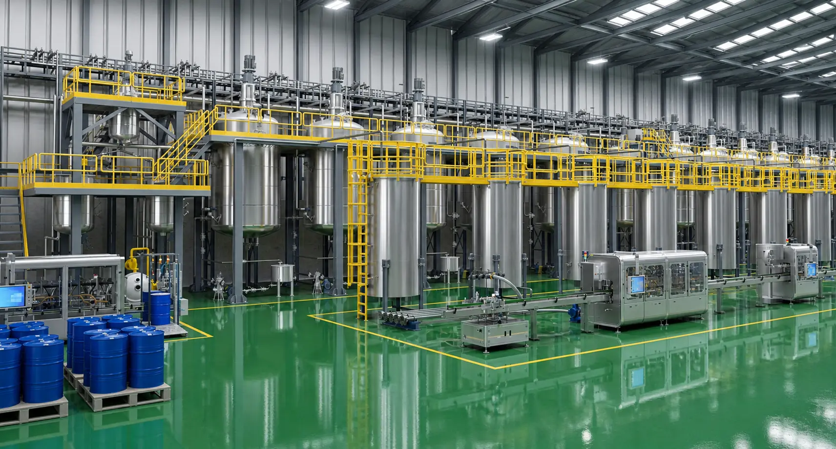
Changeover engineering controls cross-contamination through production sequencing, controlled drainage, compatible displacement, circulation cleaning, optional pigging and verified release of the next product path.
——Full product path
Clean the route—not only the blending tank.
The defined boundary includes the vessel, pump, heater, mixer, filter, transfer line, finished-oil tank interface and filling header. Additive circuits receive their own changeover procedure.
01
Production Sequence
Arrange compatible products to reduce cleaning demand.
02
Drain & Recover
Route pump, filter and low-point contents to the assigned recovery destination.
03
Pipeline Flushing
Use compatible base oil, next-product displacement or optional pigging.
04
Verify & Release
Confirm valve route, cleaning record and quality condition before the next recipe.
Typical changeover logic
SIMILAR FAMILY / CLOSE VISCOSITY
Drain or controlled displacement
Short verification route
HIGH TO LOW VISCOSITY
Enhanced circulation cleaning
Residual-viscosity check
DARK TO LIGHT PRODUCT
Full flush or dedicated path
Colour verification
INCOMPATIBLE ADDITIVE SYSTEM
Validated full cleaning
Laboratory confirmation
13
Automation, Recipe Control & Traceability
Process automation must know not only how much to add, but also which material, from which lot, through which route, under whose authority and into which finished-product batch.
——Control architecture
PLC & HMI Production Control
The PLC executes dosing sequences, equipment control and interlocks. The HMI provides local recipe selection, status, alarms and batch operation.
01
Field instruments
02
PLC control
03
HMI operation
04
Batch record
——Control architecture
Centralized PLC & SCADA Control
SCADA adds plant-wide supervision, historical trends, alarm management, production reporting and centralized recipe administration while PLCs retain real-time control.
01
Field / package PLC
02
Process PLC
03
SCADA servers
04
Operator stations
——Control architecture
Production-System Integration
Optional interfaces exchange authorized orders, material identities, inventory movements, laboratory status and finished-goods results with the client’s higher-level systems.
01
ERP / orders
02
MES execution
03
SCADA / PLC
04
Warehouse / quality

14
Safety, Contamination & Environmental Control
Lubricant blending is predominantly a physical process with high material utilization. The engineering focus is containment, overfill prevention, safe heating, correct routing, static control and recovery of incidental residues.
01
Tank Protection
High-level alarm, independent overfill response, bunding and controlled venting.
02
Heating Interlocks
High temperature, low level and no-flow protection prevent overheating and dry heating.
03
Pump & Filter Protection
Dry-run, blocked-line and differential-pressure monitoring protect equipment and product.
04
Routing Protection
Valve-position feedback and destination permissions prevent incorrect transfer and mixing.
04
Filling Safety
Earthing, spill containment, emergency stop and package-presence logic.
04
Residue Management
Filter elements, laboratory residues, drained additives and cleanup materials are classified and controlled.
GLOBAL COMPLIANCE BASIS · Electrical classification, explosion protection, fire protection and environmental provisions are established from actual material flash points, ventilation, site conditions and the regulations applicable at the project location. They are not fixed by a universal website value.
15
Plant Layout & Installation Conditions
Functional zoning separates receipt, storage, blending, packaging, quality control and warehouse logistics while maintaining safe access, maintainability and clear expansion routes.
A
BASE-OIL TANK FARM
B
ADDITIVE STORAGE
C
UNLOADING
D
BLENDING · FILTRATION · QUALITY
E
FINISHED-OIL TANKS
F
LAB & CONTROL ROOM
G
FILLING · PACKAGING · WAREHOUSE
——Layout logic
Material flow and people flow remain clear.
The final plot plan is developed from storage inventory, fire separation, truck movement, pipe-rack routing, lifting and maintenance access, packaging logistics and future capacity.
01Separate raw-material and finished-goods logistics
02Provide maintenance, lifting and filter-change access
03Locate laboratory and control functions at the quality gate
04Reserve tie-ins for future tanks, blend modules and filling lines
16
Supply Scope & Responsibility Boundary
Responsibilities are defined by battery limits, interface points and an agreed project matrix. Select each party to view the standard engineering boundary.
——Responsibility map
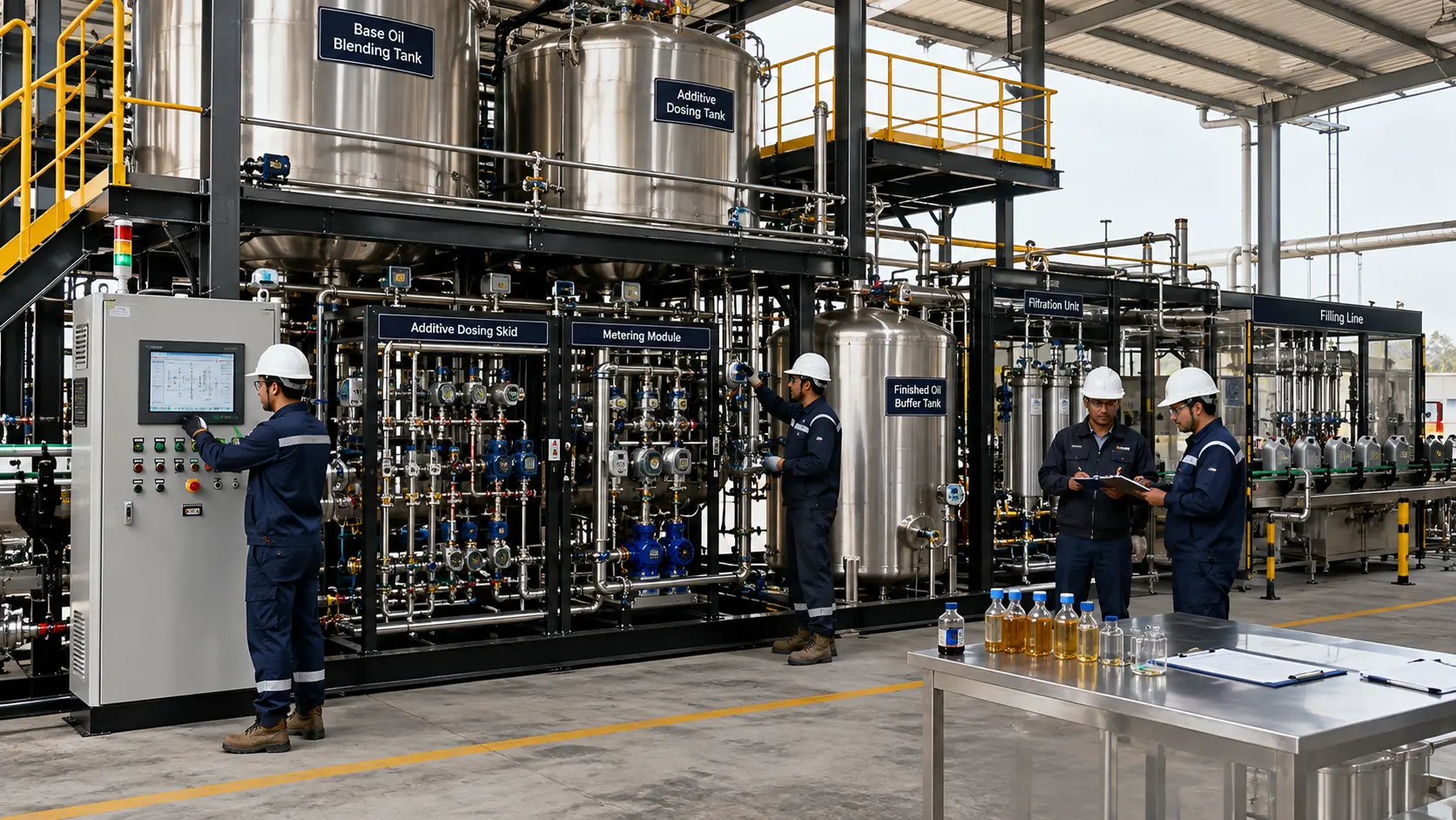
Engineered process package to defined battery limits
01 · Engineering
Process design, equipment sizing and interface documents
02 · Core Equipment
Handling, dosing, blending, filtration and cleaning modules
03 · Filling
Selected filling and packaging systems
04 · Automation
PLC/HMI or PLC/SCADA, instruments and control logic
05 · Factory Inspection
Manufacturing inspection and agreed FAT
06 · Site Services
Installation guidance, commissioning and operator training
——Responsibility map
Site, infrastructure and operating inputs
01 · Civil Works
Foundations, buildings, roads and drainage
02 · External Utilities
Power, heating medium, water, air and site distribution
03 · Fire & Compliance
Local fire system, permits and regulatory approvals
04 · Materials
Base oils, additives, packaging and approved formulations
05 · Storage / Offsites
Items outside the contracted VBOLT battery limit
06 · Local Works
Site installation labour and external interconnections as contracted
17
Project Delivery, Acceptance & Operating Support
Stage gates align client inputs, engineering documents, manufacturing, installation, trial production and performance evidence before the project moves forward.
01
CONCEPT & BASIC DESIGN
Define the production system
Feedstock, product portfolio, packaging, utility and site data become the process route, balance, layout and responsibility matrix.
02
DETAIL & MANUFACTURING
Build to approved documents
Drawings, instruments, control narratives, inspection plans and factory tests govern fabrication and release.
03
INSTALL & START UP
Prove every route and interlock
Installation checks, cleaning, cold commissioning, oil circulation, recipe trials and filling tests establish readiness.
04
ACCEPT & HAND OVER
Transfer an operable plant
Performance records, operator training, maintenance instructions, drawings and agreed quality evidence complete handover.
METERING ACCURACY
HEATING DUTY
BLEND UNIFORMITY
CHANGEOVER FUNCTION
FILLING ACCURACY
——Lubricating oil plant FAQ
Direct Answers Before Project Design
These answers explain product range, formulations, additive freedom, blending technology, filling systems, cleaning and quality boundaries in plain language.
18
Client Project Data Form
A reliable concept requires production, formulation, storage, packaging, utility, site and compliance inputs. The form organizes the first engineering discussion.
——Start with the project basis
Tell us what the plant must produce.
VBOLT converts the product portfolio and operating conditions into a modular process concept, preliminary equipment scope and project interface map.
KEY INPUTS
Country · production target · products · base oils · additive delivery · packaging · operating schedule · automation · utilities · site.