
VBOLT-DD SERIES · COMPLETE ENGINEERING SOLUTION
Waste Oil to Diesel Engineering Solution
Convert Waste Lubricating Oil into Diesel-Range Industrial Fuel.
Complete plant solutions from 1–100 TPD, including dehydration, catalytic conversion, fractionation, refining and automatic control.
1–100 TPD
Capacity
80–90%*
Typical Product Yield
PLC + SCADA
Automatic Control
EPCM
Complete Project Service
Multiple Waste Oil Feedstocks
Diesel-Range Fuel Production
NCG Reused as Heating Fuel
Project-specific capacity
01
ENGINEERING SOLUTION
Project Overview
VBOLT-DD is a complete waste oil recycling solution developed for the conversion of used lubricating oil and waste mineral oil into diesel-range industrial fuel.
Each project is engineered according to the customer’s actual feedstock, required production capacity, target product quality and site conditions, with emphasis on reliable operation, practical investment and long-term maintainability.
Backed by VBOLT’s experience in waste oil recycling equipment, the system is designed for stable production, convenient operation and maintenance, efficient energy use, high automation and environmentally responsible operation.
PROJECT PURPOSE
A Complete Waste Oil to Diesel Solution Engineered for Reliable, Efficient and Safe Operation
Each VBOLT-DD project is engineered around the customer’s feedstock, required capacity, target product quality and site conditions. The complete solution covers engineering, equipment supply, automation, safety systems, commissioning and technical support.
FEED
FEEDSTOCK
Used Lubricating Oil & Waste Mineral Oil
Feedstock analysis before final design
CONVERSION
PRODUCT
Diesel-Range Industrial Fuel
Product quality depends on feedstock and selected configuration
PRODUCT
CAPACITY
Project-Specific Capacity
Designed according to required throughput
CAPACITY
PROJECT DELIVERY
Complete Engineering Solution
Design · Manufacturing · Commissioning · Training
02
ENGINEERING SOLUTION
Design Basis & Feedstock Conditions
Plant capacity, equipment size, energy demand and product distribution are calculated only after representative feedstock data and operating conditions are defined.
Applicable Feedstocks
01 Waste engine oil
02Used lubricating oil
02Waste hydraulic oil
02Waste gear oil
02Waste transmission oil
02Tested waste mineral-oil blends
REQUIRED FEEDSTOCK TESTS
Test the oil before sizing the plant.
| Test Item | Engineering Use |
| Solids / ash | Filtration and residue system |
| Density / viscosity | Pumping, heat transfer and atomization |
| Sulfur | Need for optional desulfurization |
| Distillation range | Product distribution and cut points |
| Flash point | Safety and light-component assessment |
| Metals / additives | Catalyst and operating impact |
03
ENGINEERING SOLUTION
Target Product & Applications
The standard product is described as diesel-range industrial fuel / light distillate. Automotive-diesel classification requires full compliance with the applicable local fuel standard and independent testing.
Product quality is not defined by color alone.
The standard product is described as diesel-range industrial fuel / light distillate. Automotive-diesel classification requires full compliance with the applicable local fuel standard and independent testing.
APPLICATION
Industrial burners, boilers and other uses where diesel-range industrial fuel is permitted.
BOUNDARY
The standard solution does not automatically claim automotive-diesel compliance.
01
Appearance
02
Density
03
Viscosity
04
Flash Point
05
Water
06
Mechanical Impurities
07
Sulfur
08
Distillation Range
04
ENGINEERING SOLUTION
Complete Process Flow
The standard route is reception and testing, sedimentation and filtration, vacuum dehydration, atmospheric distillation, catalytic cracking, fractionation and condensation, optional refining, and product storage.
PROCESS UNIT 01
Waste Oil Reception & Testing
Receive, sample and classify each feedstock before it enters the process.
INPUT
Used lubricating oil / waste mineral oil
OUTPUT
Accepted or isolated feedstock
CONTROL
Water, solids, density, viscosity, sulfur and distillation range
1 / 8
PROCESS UNIT 02
Sedimentation & Filtration
Remove free solids, sludge and suspended mechanical impurities before thermal treatment.
INPUT
Accepted waste oil
OUTPUT
Pre-treated oil and filter residue
CONTROL
Settling time, filter differential pressure and element condition
2 / 8
PROCESS UNIT 03
Vacuum Dehydration & Light Fraction Removal
Remove water and low-boiling components before high-temperature processing.
INPUT
Pre-treated waste oil
OUTPUT
Dehydrated oil, water and light fraction
CONTROL
Temperature, vacuum, level and condensation
3 / 8
PROCESS UNIT 04
Atmospheric Distillation
Make the preliminary boiling-range cut and provide stable feed to catalytic conversion.
INPUT
Dehydrated oil
OUTPUT
Conversion feed and separated fractions
CONTROL
Bottom temperature, top temperature, pressure and reflux
4 / 8
PROCESS UNIT 05
Catalytic Cracking
Molecular Structure Conversion
Convert selected heavy hydrocarbon molecules into lighter diesel-range components under controlled catalytic conditions.
INPUT
Distilled conversion feed
OUTPUT
Cracked oil vapor
CONTROL
Reaction temperature, pressure, residence time and catalyst condition
5 / 8
PROCESS UNIT 06
Fractionation & Condensation
Separate cracked vapor by target boiling range and recover liquid streams through staged condensation.
INPUT
Cracked oil vapor
OUTPUT
Diesel-range product, light fraction, non-condensable gas and heavy fraction
CONTROL
Top temperature, reflux ratio, condensation temperature and system pressure
6 / 8
PROCESS UNIT 07
Optional Product Refining
Select silica-gel refining or oxidative desulfurization according to appearance, stability and sulfur targets.
INPUT
Fractionated diesel-range liquid
OUTPUT
Refined product and refining residue
CONTROL
Reagent dosage, contact time, filter pressure and oxidation conditions
7 / 8
PROCESS UNIT 08
Product Storage
Transfer released product to the client’s finished-product storage system with batch and test records.
INPUT
Qualified diesel-range liquid
OUTPUT
Diesel-range industrial fuel / light distillate
CONTROL
Batch, level, temperature, sampling and release
8 / 8
05
ENGINEERING SOLUTION
Process Unit Description
Select a process unit to see exactly what it does, what enters and leaves it, which equipment is used and what must be controlled.
PROCESS UNIT 01
Waste Oil Reception & Testing
PURPOSE
Receive, sample and classify each feedstock before it enters the process.
FEED
Used lubricating oil / waste mineral oil
OUTPUT
Accepted or isolated feedstock
KEY CONTROL
Water, solids, density, viscosity, sulfur and distillation range
PROCESS UNIT 02
Sedimentation & Filtration
PURPOSE
Remove free solids, sludge and suspended mechanical impurities before thermal treatment.
FEED
Accepted waste oil
OUTPUT
Pre-treated oil and filter residue
KEY CONTROL
Settling time, filter differential pressure and element condition
PROCESS UNIT 03
Vacuum Dehydration & Light Fraction Removal
PURPOSE
Remove water and low-boiling components before high-temperature processing.
FEED
Pre-treated waste oil
OUTPUT
Dehydrated oil, water and light fraction
KEY CONTROL
Temperature, vacuum, level and condensation
PROCESS UNIT 04
Atmospheric Distillation
PURPOSE
Make the preliminary boiling-range cut and provide stable feed to catalytic conversion.
FEED
Dehydrated oil
OUTPUT
Conversion feed and separated fractions
KEY CONTROL
Bottom temperature, top temperature, pressure and reflux
PROCESS UNIT 05
Catalytic Cracking
Molecular Structure Conversion
PURPOSE
Convert selected heavy hydrocarbon molecules into lighter diesel-range components under controlled catalytic conditions.
FEED
Distilled conversion feed
OUTPUT
Cracked oil vapor
KEY CONTROL
Reaction temperature, pressure, residence time and catalyst condition
PROCESS UNIT 06
Fractionation & Condensation
PURPOSE
Separate cracked vapor by target boiling range and recover liquid streams through staged condensation.
FEED
Cracked oil vapor
OUTPUT
Diesel-range product, light fraction, non-condensable gas and heavy fraction
KEY CONTROL
Top temperature, reflux ratio, condensation temperature and system pressure
PROCESS UNIT 07
Optional Product Refining
PURPOSE
Select silica-gel refining or oxidative desulfurization according to appearance, stability and sulfur targets.
FEED
Fractionated diesel-range liquid
OUTPUT
Refined product and refining residue
KEY CONTROL
Reagent dosage, contact time, filter pressure and oxidation conditions
PROCESS UNIT 08
Product Storage
PURPOSE
Transfer released product to the client’s finished-product storage system with batch and test records.
FEED
Qualified diesel-range liquid
OUTPUT
Diesel-range industrial fuel / light distillate
KEY CONTROL
Batch, level, temperature, sampling and release
OPTIONAL REFINING
Select refining by the required product target.
Silica-gel refining improves appearance and stability. Oxidative desulfurization is selected only where a defined sulfur-reduction target justifies the added system.
Silica-Gel Refining
Activated silica gel adsorbs polar compounds and unstable components. Precision filtration separates the spent adsorbent from the polished product.
06
ENGINEERING SOLUTION
Material Balance
For every representative 10 tonnes of waste oil processed, the page shows the quantity of diesel-range product, water, light fraction, non-condensable gas and heavy residue and where each stream goes.
INPUT BASIS
10.0 t
Waste Oil Feed
One representative operating-day balance.
Diesel-range product
8.0–8.5 t 80%–85%
Product testing → optional refining → storage
Separated water
<0.5 t <5%
Vacuum dehydration → wastewater treatment
Light fraction
≈0.5 t≈5%
Separate collection → reuse or treatment
Non-condensable gas
0.3–0.5 t3%–5%
Safe recovery → process heating
Heavy residue
0.2–0.5 t2%–5%
Asphalt use, boiler fuel or compliant handling
10-TONNE EXAMPLE
Typical values for project evaluation. Actual quantities depend on feedstock water, composition and operating conditions. The final closed material balance is established after representative feedstock testing.
| Stream | Quantity from 10.0 t Feed | Share of Feed | Destination |
|---|---|---|---|
| Diesel-range product | 8.0–8.5 t | 80%–85% | Testing, optional refining and product storage |
| Separated water | <0.5 t | <5% | VBOLT wastewater treatment package or site treatment |
| Light fraction | ≈0.5 t | ≈5% | Separate collection for reuse or treatment |
| Non-condensable gas | 0.3–0.5 t | 3%–5% | Recovered as process fuel |
| Heavy residue | 0.2–0.5 t | 2%–5% | Asphalt use, boiler fuel or compliant handling |
07
ENGINEERING SOLUTION
Utilities & Energy Consumption
The utility schedule covers electricity, heating fuel, circulating cooling water, instrument air, nitrogen and catalyst or refining consumables, each tied to a defined operating condition.
| Utility | Users | Project Output | Main Variables |
|---|---|---|---|
| Electricity | Pumps, fans, vacuum package, PLC | Installed load, running load, kWh/t | Capacity, vacuum and automation |
| Heating fuel | Distillation, cracking, heat tracing | Fuel type, heating value, hourly use | Feed water, heat recovery and load |
| Cooling water | Condensers, product coolers, vacuum system | Circulation, makeup, supply/return temperature | Ambient temperature and condensing duty |
| Instrument air | Control valves and instruments | Pressure, normal and peak flow | Valve count and action frequency |
| Nitrogen | Start-up/shutdown purging | Pressure and purge quantity | Equipment volume and purge procedure |
| Catalyst / refining media | Conversion and optional refining | Consumption per batch or tonne | Feedstock and product target |
10 T/D REFERENCE
250 kWh/d
Electricity at 25 kWh/t
10 T/D REFERENCE
200 kg/d
External fuel at 20 kg/t
RECIRCULATING
40 t/d
Cooling-water reference
10 T/D REFERENCE
0.15 t/d
Catalyst reference
REFERENCE BASIS
These figures are preliminary references for a comparable 10 T/D configuration, not universal guarantees. Final consumption is calculated from feedstock water, product distribution, heat recovery, ambient conditions and selected equipment.
08
ENGINEERING SOLUTION
Major Equipment Configuration
The equipment list identifies each tag, equipment name, process duty, quantity basis and whether the item is standard or optional.
| Section | Tag | Equipment | Duty | Quantity | Scope |
|---|---|---|---|---|---|
| Feedstock | TK-101 | Feedstock receiving/buffer unit | Receiving, homogenization and stable feed | Project-specific | Standard |
| Feedstock | F-101 | Pre-filter | Mechanical impurity removal | Project-specific | Standard |
| Dehydration | V-201 | Vacuum dehydration unit | Water and light-component removal | Project-specific | Standard |
| Dehydration | E-201 | Condensation and separation system | Water-vapor and light-fraction recovery | Project-specific | Standard |
| Conversion | T-301 | Atmospheric distillation system | Preliminary boiling-range separation | Project-specific | Standard |
| Conversion | R-401 | Catalytic cracking reactor | Heavy-hydrocarbon molecular conversion | Project-specific | Standard |
| Recovery | C-501 | Fractionation column | Target boiling-range separation | Project-specific | Standard |
| Recovery | E-501 | Multi-stage condenser system | Liquid recovery and NCG separation | Project-specific | Standard |
| Refining | U-601 | Silica-gel refining system | Appearance and stability improvement | By product target | Optional |
| Refining | U-602 | Oxidative desulfurization system | Sulfur reduction | By sulfur target | Optional |
| Utilities | VP-701 | Vacuum package | Establish and maintain vacuum | Project-specific | Standard |
| Utilities | FG-801 | NCG safety recovery system | Separation, flame arresting, regulation and fuel reuse | Project-specific | Standard |
| Section | Tag | Equipment | Duty | Quantity | Scope |
|---|---|---|---|---|---|
| Feedstock | TK-101 | Feedstock receiving/buffer unit | Receiving, homogenization and stable feed | Project-specific | Standard |
| Feedstock | F-101 | Pre-filter | Mechanical impurity removal | Project-specific | Standard |
| Section | Tag | Equipment | Duty | Quantity | Scope |
|---|---|---|---|---|---|
| Dehydration | V-201 | Vacuum dehydration unit | Water and light-component removal | Project-specific | Standard |
| Dehydration | E-201 | Condensation and separation system | Water-vapor and light-fraction recovery | Project-specific | Standard |
| Section | Tag | Equipment | Duty | Quantity | Scope |
|---|---|---|---|---|---|
| Conversion | T-301 | Atmospheric distillation system | Preliminary boiling-range separation | Project-specific | Standard |
| Conversion | R-401 | Catalytic cracking reactor | Heavy-hydrocarbon molecular conversion | Project-specific | Standard |
| Section | Tag | Equipment | Duty | Quantity | Scope |
|---|---|---|---|---|---|
| Recovery | C-501 | Fractionation column | Target boiling-range separation | Project-specific | Standard |
| Recovery | E-501 | Multi-stage condenser system | Liquid recovery and NCG separation | Project-specific | Standard |
| Section | Tag | Equipment | Duty | Quantity | Scope |
|---|---|---|---|---|---|
| Refining | U-601 | Silica-gel refining system | Appearance and stability improvement | By product target | Optional |
| Refining | U-602 | Oxidative desulfurization system | Sulfur reduction | By sulfur target | Optional |
| Section | Tag | Equipment | Duty | Quantity | Scope |
|---|---|---|---|---|---|
| Utilities | VP-701 | Vacuum package | Establish and maintain vacuum | Project-specific | Standard |
| Utilities | FG-801 | NCG safety recovery system | Separation, flame arresting, regulation and fuel reuse | Project-specific | Standard |
Material, design temperature, design pressure, area, motor power and interfaces are defined in individual equipment datasheets.
09
ENGINEERING SOLUTION
Automation & Control System
Choose local PLC + HMI control or a plant-wide PLC + SCADA system. The PLC executes real-time control and interlocks; SCADA adds centralized monitoring, history, alarm management and reporting.
STANDARD CONTROL
PLC + HMI
Local plant operation with real-time control, alarms, interlocks and operating records.
CONTROL ARCHITECTURE
01
Field Instruments
02
PLC & Remote I/O
03
Local HMI
PLC: real-time control, sequences and interlocks.
HMI: operation, monitoring and records.
STANDARD CONTROL
PLC + SCADA
Plant-wide supervision with centralized monitoring, historical data, alarm management and production reporting.
CONTROL ARCHITECTURE
01
Field Instruments
02
PLC & Remote I/O
03
Industrial Network
04
SCADA Server
05
Operator / Engineer Stations
PLC: real-time control, sequences and interlocks.
SCADA: operation, monitoring and records.
Temperature
Pressure & Vacuum
Level
Flow
Combustion
Emergency Shutdown
10
ENGINEERING SOLUTION
Safety Interlocks & Off-Gas Treatment
The safety system defines exactly how the plant alarms, isolates heat and feed, and moves to a safe state after high temperature, high pressure, vacuum failure, flame failure or cooling-water loss.
STANDARD NCG SAFETY TRAIN
Entrained liquid is removed before the gas passes through separation, flame arresting, isolation, pressure regulation and buffering. Low pressure, high pressure and flame-failure signals are interlocked with the burner.
| Trigger | Automatic Action | Protection Purpose |
|---|---|---|
| Reactor temperature high-high | Alarm, stop feed and cut heating | Prevent overheating and thermal runaway |
| System pressure high-high | Cut heat, stop feed and enter safe relief logic | Prevent equipment overpressure |
| Abnormal vacuum | Alarm, limit heat load and inspect condensation/vacuum package | Prevent unstable distillation |
| Burner flame failure | Close fuel and NCG automatic shut-off valves | Prevent unburned gas from entering the furnace |
| NCG pressure low/high | Isolate NCG fuel and move to safe state | Maintain stable fuel-gas operation |
| Cooling-water failure | Alarm and reduce or stop heat input | Prevent loss of condensation |
| Critical level high-high/low-low | Stop related pump or feed | Prevent overflow and dry running |
| Emergency shutdown | Isolate feed, heat and combustible gas through ESD logic | Bring the plant to a controlled safe state |
11
ENGINEERING SOLUTION
Waste Treatment & Resource Recovery
The plant can combine wastewater treatment, off-gas energy recovery, flue-gas alkali scrubbing and heavy-residue utilization in one environmental-control system.
PROCESS PLANT
Three controlled outlet routes
01 WASTEWATER
Secondary Discharge
Vacuum-dehydration condensate and oily drainage
VBOLT OPTIONAL SUPPLY Designed to meet the applicable secondary discharge standard after water analysis.
02 OFF-GAS & FLUE GAS
Fuel Recovery + Alkali Scrubbing
NCG is recovered as process fuel; combustion flue gas is cleaned before discharge.
ENERGY RECOVERY Demisting, separation, flame arresting and pressure control protect the fuel-gas route.
03 HEAVY RESIDUE
Resource Utilization
Heavy distillation residue is collected separately from filter solids and spent media.
ASPHALT PLANT
Raw material for asphalt blending or road paving
BOILER FUEL
Industrial energy recovery when properties and local rules permit
ENERGY RECOVERY Demisting, separation, flame arresting and pressure control protect the fuel-gas route.
Final wastewater and air-emission limits, residue classification and utilization routes follow the project location’s regulations and representative laboratory analysis.
12
ENGINEERING SOLUTION
Plant Layout & Installation Conditions
The layout follows process flow, safety spacing, operating access, lifting and maintenance routes, utility tie-ins and future expansion requirements.
01 Feedstock & Pre-treatment
02 Distillation & Conversion
03Fractionation & Refining
04 Heating & Off-Gas
05 Control & Utilities
06 Client Tank Farm & Loading
Required Client Site Conditions
Site dimensions and soil data · transport and lifting access · foundations · power and grounding · cooling-water tie-ins · fuel tie-ins · instrument air · fire protection · tanks and loading facilities
13
ENGINEERING SOLUTION
What VBOLT Supplies
VBOLT supplies the engineered process plant, in-skid systems, selected automation and project services up to clearly marked connection points.
VBOLT SUPPLY
Inside the process-plant boundary
Engineering, process equipment, auxiliaries, automation and project services are supplied to the defined battery limits.
01
Engineering & Documents
Process design, layout, datasheets, control logic and interface documents
02
Main Process Equipment
Pre-treatment, dehydration, distillation, cracking, fractionation and condensation
03
Auxiliary Systems
Vacuum, heating, condensation, NCG recovery and product transfer
04
Automation & Safety
PLC/HMI or PLC/SCADA, instruments, alarms and safety interlocks
05
In-Skid Piping
Piping, valves, supports and connections inside the equipment boundary
06
Commissioning & Training
Installation guidance, trial operation, acceptance support and operator training
CLIENT CONSTRUCTION
What the Client Needs to Build
The client constructs the foundations, tank farm, loading area, external utilities, fire-protection system and site connections shown in blue.
01
Civil Works & Foundations
Site grading, equipment foundations, plant building, roads and drainage
02
Plant Building & Steelwork
Operating platforms, stairs and site structural steel outside VBOLT skids
03
Feedstock & Product Tank Farm
Waste-oil tanks, product tanks, light-fraction tanks and tank-farm piping
04
Loading & Unloading Area
Truck unloading, product loading, transfer pumps and site piping
05
External Utilities
Power, fuel, cooling water, instrument air, nitrogen and drainage connections
06
Fire Protection & Site Safety
Fire water, extinguishing systems, alarms, grounding and emergency access
15
ENGINEERING SOLUTION
Installation, Commissioning & Acceptance
Four controlled stages define the work, deliverables, client support and release gate from approved design to final plant handover.
TURNKEY DELIVERY CONTROL
From Design Freeze to Plant Handover
STAGE 01
Engineering
Confirm feedstock, capacity, product target, utilities and site interfaces.
DELIVERABLE
Installation checks, test records and commissioning report
CLIENT SUPPORT
Provide utilities, qualified feedstock and operating personnel
RELEASE GATE
Stable operation
STAGE 02
Manufacturing & Delivery
Fabricate, inspect, pressure-test, preserve, mark, pack and ship the equipment.
DELIVERABLE
Equipment, inspection dossier and packing list
CLIENT SUPPORT
Complete the site and prepare lifting and receiving resources
RELEASE GATE
Ready for shipment
STAGE 03
Installation & Start-up
Verify installation, complete cold testing, hot circulation and gradual feed-in.
DELIVERABLE
Installation checks, test records and commissioning report
CLIENT SUPPORT
Provide utilities, qualified feedstock and operating personnel
RELEASE GATE
Stable operation
STAGE 04
Acceptance & Handover
Run under agreed conditions, sample the product and complete operator training.
DELIVERABLE
Performance record, test results and operating documents
CLIENT SUPPORT
Participate in sampling, testing and final sign-off
RELEASE GATE
Acceptance signed
16
ENGINEERING SOLUTION
Operators & Maintenance
Staffing and maintenance are defined by plant capacity, operating mode, automation level, local work rules and the client’s existing maintenance and laboratory resources.
Operating Roles
| Role | Main Duty | Basis |
|---|---|---|
| Shift Supervisor | Start-up, shutdown, adjustment and handover | Per shift |
| Field Operator | Inspection, sampling, drains, filtration and transfer | By plant size |
| Electrical / Instrument | PLC, instruments, motors and interlocks | Shared or dedicated |
| Mechanical | Pumps, valves, exchangers and rotating equipment | Shared or dedicated |
| Laboratory | Feed, process and product testing | By laboratory plan |
Maintenance Frequency
| Frequency | Main Work |
|---|---|
| Each Shift | Temperature, pressure, level, pumps, leaks, flame and alarms |
| Weekly | Filter differential pressure, drains, flame arrester and standby equipment |
| Monthly | Valve stroke, interlock test, instrument comparison and electrical tightening |
| Quarterly | Heat exchangers, vacuum system, combustion and safety accessories |
| Annual | Planned shutdown, internal inspection, calibration and interlock validation |
17
ENGINEERING SOLUTION
Project References & Third-Party Testing
A credible project reference connects the site photographs to the feedstock, plant capacity, process configuration, operating record and corresponding product test report.
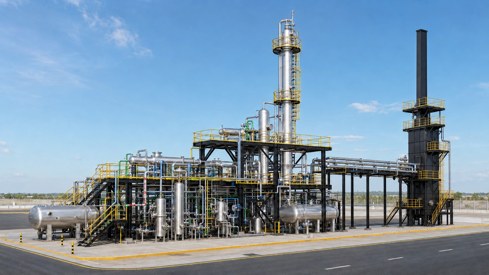
Third-Party Verification
Every published result should identify sample source, sampling date, test method, report number and associated project batch.
18
ENGINEERING SOLUTION
Client Project Data Form
Submit feedstock, capacity, product target, utilities and site data so VBOLT can define the process configuration, equipment sizes, consumption and battery limits.
PROJECT INPUT
Engineering starts with real project data.
Better feedstock data produces a more reliable material balance, equipment list, energy estimate and product assessment.
01 Feedstock & Capacity
02 Product & Refining
03Utilities & Site
04 Contact & Requirements