

VBT-DD SERIES · 5–200+ TPD INDUSTRIAL PLANTS
Waste Oil to Diesel Plant
Convert waste oil into diesel through an integrated system combining preparation, distillation, catalytic conversion, fractionation and selected refining.
Diesel Output
Euro III or Euro V / EN 590 route
80–85% Recovery
Reference diesel recovery rate
PLC / SCADA
Centralized process automation
EPCM Services
Engineering to commissioning
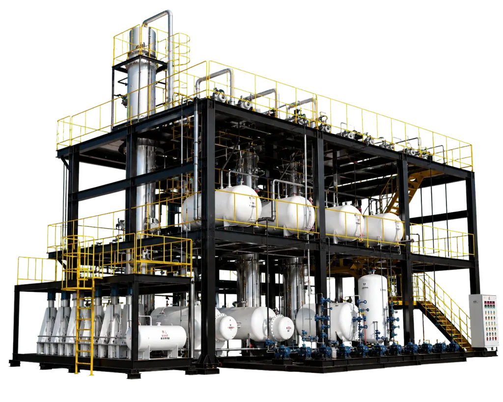
Waste Oil to Diesel Plant
An integrated industrial plant engineered to convert waste oil into diesel through distillation, catalytic conversion, fractionation and refining.
STANDARD REFINING ROUTE
Euro III Diesel
Adsorptive refining configuration
DESULFURIZATION ROUTE
Euro V / EN 590 Diesel
Diesel desulfurization configuration
Diesel as the Main Product
The complete process is designed around producing a marketable diesel fraction.
Flexible Diesel Quality Route
Select standard refining or desulfurization according to the required diesel grade.
Integrated Energy Recovery
The separated light fraction can be reused as plant fuel to support the heating system.
80–85%
DIESEL RECOVERY RATE
5–200+ TPD
PROCESSING CAPACITY
PLC / SCADA
CONTROL SYSTEM
EPCM
PROJECT SERVICES
———— Plant Film · Actual Project
WATCH THE PLANT IN OPERATION
04:05 MIN ·Full Project Film
VBOLT Project Film
Real Equipment · Real Process · Real Operation
———— Plant Film
Waste Oil Re-Refining Plant
See the complete operating workflow from feedstock pretreatment and vacuum distillation to fraction recovery and final product handling — presented directly inside the page, not as a separate video block.
Feedstock
Waste Lubricating Oil
Process
Vacuum Distillation
Output
Base Oil / Diesel-Range Product
Configuration
Modular · Skid-Mounted
———— 02 · Process Intelligence
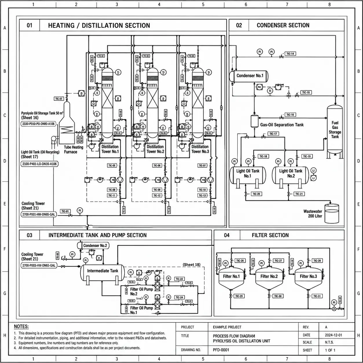
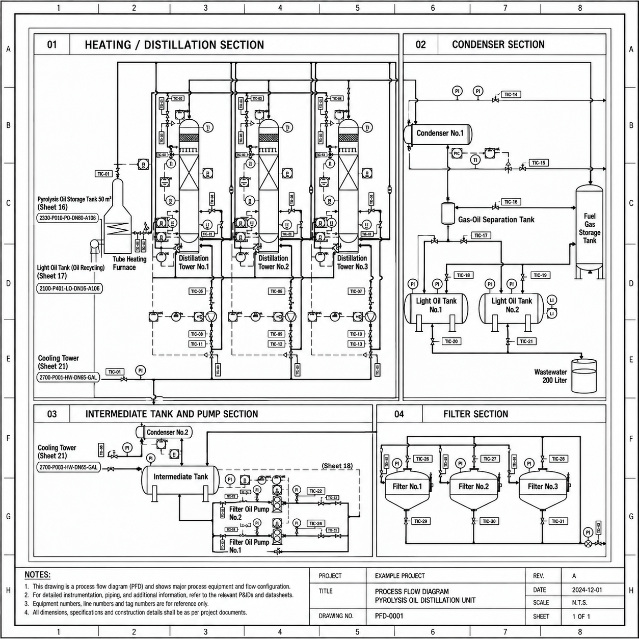
Inside the Waste Oil to Diesel Process
Trace the material through the plant. Each operating stage is connected to one commercial objective: stable diesel production.
01
STAGE 01 · MATERIAL IN
Feed Preparation
Waste oil is screened, settled and transferred into the plant under controlled conditions.
Screening
Settling
Controlled Transfer
PROCESS RESULT
Prepared waste oil ready for dehydration
02
STAGE 02 · PRETREATMENT
Dehydration
Water and unstable light components are removed before the waste oil enters the high-temperature section.
Controlled Heating
Water Removal
Stable Feed
PROCESS RESULT
Prepared waste oil ready for dehydration
03
STAGE 03 · 180–420°C
Distillation
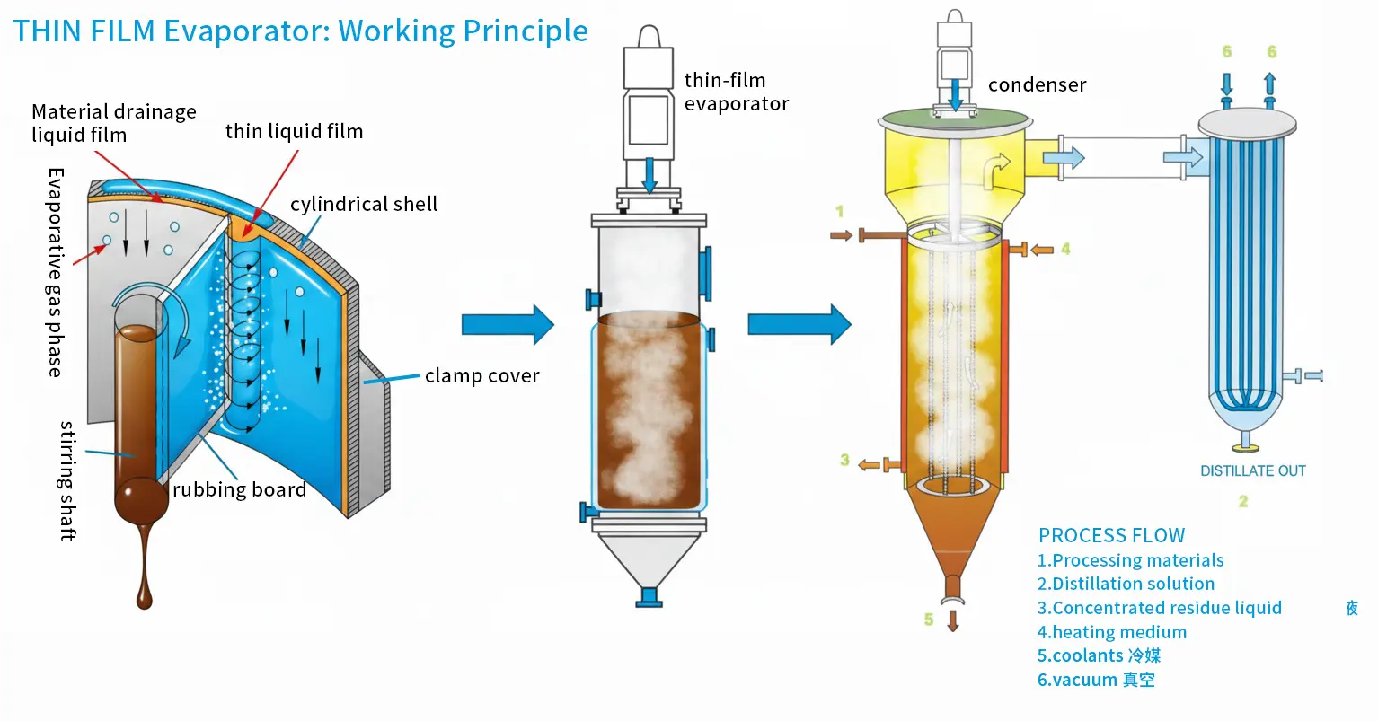
Select the tubular heating furnace or the optional thin-film distillation configuration. The tubular furnace heats waste oil directly; thin-film distillation uses indirect thermal-oil heating.
Tubular Heating Furnace
Thin-Film Distillation · Optional
180–420°C
PROCESS RESULT
Recovered vapor and liquid fractions routed to conversion
04
STAGE 04 · CONVERSION
Catalytic Cracking & Carbon-Chain Conversion
Controlled catalytic conversion adjusts the hydrocarbon distribution before fractionation.
Catalytic Cracking
Carbon-Chain Conversion
Controlled Reaction
PROCESS RESULT
Converted stream prepared for fractionation
05
STAGE 05 · SEPARATION
Fractionation System
The fractionation system separates the light fraction from the target diesel fraction.
Light Fraction
Diesel Fraction
Controlled Cut Points
PROCESS RESULT
Light fraction to plant fuel; diesel to refining
06
STAGE 06 · PRODUCT UPGRADING
Diesel Refining
Select adsorptive refining for the Euro III route or diesel desulfurization for the Euro V / EN 590 route.
Adsorptive Refining
Diesel Desulfurization
Two Quality Routes
PROCESS RESULT
Refined diesel matched to the selected route
07
STAGE 07 · PRODUCT OUT
Product Storage
Diesel is cooled, tested and transferred to the finished-product storage system.
Cooling
Product Testing
Storage
PROCESS RESULT
Diesel ready for product handling
MATERIAL IN
Waste Oil
→
CONTROLLED CONVERSION
VBT-DD Process
→
MAIN PRODUCT
Diesel · 80–85%
→
ENERGY LOOP
Light Fraction → Plant Fuel
QUALITY ROUTES
Euro III · Euro V / EN 590
———— 03 · EPCM Project Services
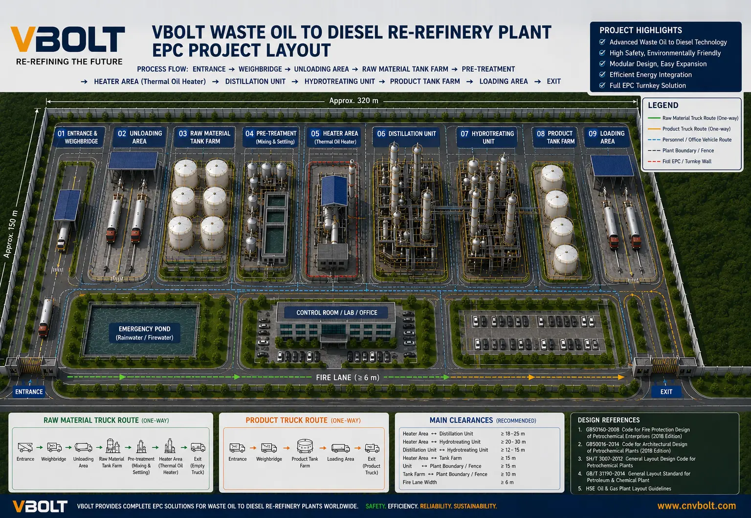
EPCM Planning for Waste Oil to Diesel Plants
VBOLT coordinates engineering, procurement, construction management and commissioning as one managed project—from the design basis to stable plant operation.
01 · PROJECT DEFINITION
Define the Project Basis
Confirm capacity, product target, site utilities and local project conditions before detailed engineering begins.
Customer outcome
A coordinated technical basis for engineering and project planning.
02 · ENGINEERING
Coordinate the Complete Plant Design
Develop process, equipment, piping, utility, electrical and PLC / SCADA engineering around one approved basis.
Customer outcome
An integrated engineering package that defines the plant.
03 · PROCUREMENT MANAGEMENT
Manage Equipment and Supplier Quality
Coordinate core equipment manufacturing, supporting procurement, inspection and documentation.
Customer outcome
A controlled equipment supply package aligned with the approved design.
04 · CONSTRUCTION MANAGEMENT
Coordinate Site Construction and Installation
Manage installation interfaces, schedule, quality supervision and site coordination under the agreed EPCM scope.
Customer outcome
A coordinated site execution path from delivered equipment to an installed plant.
05 · COMMISSIONING & SUPPORT
Bring the Plant Into Stable Operation
Support cold and hot commissioning, start-up, operator training and ongoing technical service.
Customer outcome
A commissioned plant with trained operators and structured technical support.
5–200+ TPD
Project Scale
PLC / SCADA
Control Integration
Modular Expansion
Plant Development
EPCM
PROJECT SERVICES
———— 04 · Core Technologies
Engineering That Keeps the Plant Running
Explore the technologies that control heating, conversion, separation and diesel quality—starting with VBOLT’s patented maintenance-focused furnace design.
01 Direct Waste-Oil Heating
02 Detachable Heating Section
03 Internal Coil Access
CORE TECHNOLOGY 01 · PATENTED DESIGN
Patented Detachable Tubular Heating Furnace
Waste oil is heated directly inside the tubular furnace. Unlike conventional fixed furnace structures, VBOLT’s patented heating section can be removed for inspection, decoking and internal cleaning.
01
Precision Manufacturing
Your equipment is built with industrial-grade materials and strict quality control to ensure long.
02
Detachable Structure
The heating section is engineered for removal and reinstallation.
03
Decoking & Cleaning
Internal deposits can be accessed and cleaned during maintenance.
04
Long-Term Maintainability
Simplified inspection and servicing for industrial operation.
REMOVE→DECOKE→INSPECT→REINSTALL
Built for Cleaning. Engineered for Long-Term Operation.
CORE TECHNOLOGY 02 · OPTIONAL CONFIGURATION
Thin-Film Distillation
Thermal oil indirectly heats the waste oil. Under vacuum, the oil forms a thin and continuously renewed film with short thermal residence time.
01
Indirect Heating
Thermal oil transfers heat without direct furnace contact.
02
Uniform Liquid Film
A thin film supports controlled and efficient heat transfer.
03
Short Residence Time
Reduces prolonged thermal exposure of the feedstock.
04
Reduced Local Overheating
Helps limit localized thermal stress and coking.
CORE TECHNOLOGY 03 · CONVERSION CONTROL
Catalytic Cracking & Carbon-Chain Conversion
Controlled catalytic conversion adjusts hydrocarbon distribution before fractionation, preparing the stream for recovery of the target diesel fraction.
01
Controlled Conversion
Reaction conditions are coordinated around the process route.
02
Carbon-Chain Adjustment
Supports a product distribution suited to diesel recovery.
03
Fractionation Preparation
Creates a controlled feed for the downstream separation stage.
CORE TECHNOLOGY 04 · PRODUCT QUALITY
Fractionation & Diesel Refining
Fractionation separates the light fraction from diesel. The light fraction is recovered as plant fuel, while diesel follows the selected refining route.
01
Light-Fraction Recovery
Recovered light fraction can support the plant heating system.
02
Euro III Route
Adsorptive refining configuration for standard diesel production.
03
Euro V / EN 590 Route
Desulfurization and finishing configuration for upgraded diesel.
———— 05 · VBT-DD Series Configurations
Select the Appropriate Plant Scale
Each model now displays the project indicators that actually change with processing scale: capacity, footprint, installed power, heating load, staffing and delivery format.
SELECTED CONFIGURATION
VBT-DD-05
Compact commercial waste oil to diesel plant with a nominal processing capacity of 5 tonnes per day.
Processing Capacity
5 TPD*
Reference Footprint
180–260 m²*
Heating Load
200,000–250,000 kcal/h*
Control System
PLC / SCADA*
Recommended Project
Small commercial plant*
Installed Power
45–65 kW*
Operators Required
2–3 persons/shift*
Delivery Format
Modular skid package*
* Preliminary selection data for layout and comparison. Final footprint, power, heating load and staffing are confirmed during EPCM engineering.
SELECTED CONFIGURATION
VBT-DD-10
Standard commercial plant for regional waste-oil collection and continuous diesel production.
Processing Capacity
10 TPD*
Reference Footprint
260–380 m²*
Heating Load
350,000–450,000 kcal/h*
Control System
PLC / SCADA*
Recommended Project
Small commercial plant*
Installed Power
80–120 kW*
Operators Required
3 persons/shift*
Delivery Format
Modular skid + site connection*
* Preliminary selection data for layout and comparison. Final footprint, power, heating load and staffing are confirmed during EPCM engineering.
SELECTED CONFIGURATION
VBT-DD-20
Medium industrial plant for centralized waste-oil collection and continuous production.
Processing Capacity
20 TPD*
Reference Footprint
450–650 m²*
Heating Load
600,000–800,000 kcal/h*
Control System
PLC / SCADA*
Recommended Project
Medium industrial plant*
Installed Power
150–220 kW*
Operators Required
3–4 persons/shift*
Delivery Format
Modular sections + site installation*
* Preliminary selection data for layout and comparison. Final footprint, power, heating load and staffing are confirmed during EPCM engineering.
SELECTED CONFIGURATION
VBT-DD-30
Industrial configuration for expanded continuous diesel production.
Processing Capacity
30 TPD*
Reference Footprint
650–900 m²*
Heating Load
900,000–1,200,000 kcal/h*
Control System
PLC / SCADA*
Recommended Project
Large industrial plant*
Installed Power
220–320 kW*
Operators Required
4–5 persons/shift*
Delivery Format
Factory modules + site-built systems*
* Preliminary selection data for layout and comparison. Final footprint, power, heating load and staffing are confirmed during EPCM engineering.
SELECTED CONFIGURATION
VBT-DD-50
Large industrial configuration with expanded utilities and storage integration.
Processing Capacity
50 TPD*
Reference Footprint
950–1,300 m²*
Heating Load
1,500,000–2,000,000 kcal/h*
Control System
PLC / SCADA*
Recommended Project
Regional processing center*
Installed Power
350–500 kW*
Operators Required
5–6 persons/shift*
Delivery Format
Modular plant + EPCM services*
* Preliminary selection data for layout and comparison. Final footprint, power, heating load and staffing are confirmed during EPCM engineering.
SELECTED CONFIGURATION
VBT-DD-100
High-capacity processing plant engineered for continuous industrial operation.
Processing Capacity
100 TPD*
Reference Footprint
1,600–2,300 m²*
Heating Load
3,000,000–4,000,000 kcal/h*
Control System
PLC / SCADA*
Recommended Project
Large processing complex*
Installed Power
650–900 kW*
Operators Required
7–9 persons/shift*
Delivery Format
Project-engineered EPCM configuration*
* Preliminary selection data for layout and comparison. Final footprint, power, heating load and staffing are confirmed during EPCM engineering.
SELECTED CONFIGURATION
VBT-DD-200
Large-scale waste oil to diesel project with site-specific plant integration.
Processing Capacity
200 TPD*
Reference Footprint
2,800–4,000 m²*
Heating Load
6,000,000–8,000,000 kcal/h*
Control System
PLC / SCADA*
Recommended Project
Industrial processing complex*
Installed Power
1,200–1,700 kW*
Operators Required
10–14 persons/shift*
Delivery Format
Complete EPCM project services*
* Preliminary selection data for layout and comparison. Final footprint, power, heating load and staffing are confirmed during EPCM engineering.
SELECTED CONFIGURATION
VBT-DD CUSTOM EPCM
Project-specific plant for processing capacities above 200 TPD or complex site requirements.
Processing Capacity
200+ TPD*
Reference Footprint
Project-specific*
Heating Load
Engineering calculation*
Control System
PLC / SCADA*
Recommended Project
Custom EPCM project*
Installed Power
Engineering calculation*
Operators Required
Project-specific*
Delivery Format
Complete EPCM project services*
* Preliminary selection data for layout and comparison. Final footprint, power, heating load and staffing are confirmed during EPCM engineering.
———— 06 · Technical Data
Engineering Information at a Glance
| Parameter | Reference Value* | Remarks |
|---|---|---|
| Plant series | VBT-DD Series | Standard models and custom EPCM projects |
| Processing capacity | 5–200+ TPD | Model and project dependent |
| Diesel recovery rate | 80–85 wt% | Reference operating range |
| Distillation temperature | 180–420°C | Selected distillation configuration |
| Distillation technology | Tubular heating furnace / thin-film distillation | Thin-film distillation is optional |
| Operating hours | 8,000 h/year | Subject to operating plan |
| Main product | Diesel | Euro III or Euro V / EN 590 route |
* Preliminary reference data for comparison and engineering discussion.
| Utility | Reference Requirement* | Remarks |
|---|---|---|
| Electrical power | Model-specific | See VBT-DD configuration selector |
| Heating load | Model-specific | Dependent on selected plant configuration |
| Cooling water circulation | 6–12 m³/t feed | Closed-loop circulation |
| Instrument air | 0.6–0.8 MPa | Dry compressed air |
| Operator requirement | Model-specific | Automation and scale dependent |
* Preliminary reference data for comparison and engineering discussion.
| EPCM Service | Typical Status* | Remarks |
|---|---|---|
| Engineering | Available | Process, equipment, layout, utilities and control |
| Procurement management | Available | Vendor coordination and quality management |
| Construction management | Project-defined | Site coordination, schedule and quality supervision |
| PLC / SCADA integration | Included | Centralized control and field instruments |
| Commissioning & training | Available | Start-up support and operator training |
* Preliminary reference data for comparison and engineering discussion.
———— 07 · Feedstock, Configuration & Diesel Output
From Feedstock to a Defined Diesel Route
Select a representative feedstock to see how VBOLT connects oil evaluation, process configuration and the target diesel route.
02 · RECOMMENDED CONFIGURATION
Waste Oil Pretreatment + Selected Distillation + Diesel Refining
Reference configuration for used engine-oil feedstock.
Feedstock Evaluation
Confirm water, sludge, sulfur, chlorine, metals and distillation range.
Selected Distillation
Select the tubular heating furnace or optional thin-film distillation at 180–420°C.
Conversion & Fractionation
Apply catalytic carbon-chain conversion and separate light and diesel fractions.
Diesel Refining Route
Select adsorptive refining or diesel desulfurization from the target quality.
02 · RECOMMENDED CONFIGURATION
Dehydration + Selected Distillation + Diesel Refining
Configurable used motor oil to diesel route.
Feedstock Evaluation
Remove water, sludge and unstable contaminants before distillation.
Selected Distillation
Select the tubular heating furnace or optional thin-film distillation.
Conversion & Fractionation
Recover light fraction for plant fuel and separate the diesel fraction.
Diesel Refining Route
Select adsorptive refining or diesel desulfurization from the target grade.
02 · RECOMMENDED CONFIGURATION
Feed Conditioning + Distillation Route + Product Refining
Evaluation route for mixed waste lubricating-oil collections.
Feedstock Evaluation
Characterize water, solids, sulfur, metals and mixed lubricant content.
Selected Distillation
Choose the distillation technology from the confirmed feed assay.
Conversion & Fractionation
Control catalytic conversion and fraction cut points for diesel recovery.
Diesel Refining Route
Configure the refining route from the required diesel target.
02 · RECOMMENDED CONFIGURATION
Enhanced Pretreatment + Project-Specific Distillation
Project-specific route for variable industrial waste-oil streams.
Feedstock Evaluation
Review the source and apply enhanced settling, filtration and dehydration.
Selected Distillation
Select the appropriate distillation route after laboratory screening.
Conversion & Fractionation
Control conversion and fractionation around the confirmed oil composition.
Diesel Refining Route
Use the required diesel-refining route only after product-target confirmation.
02 · RECOMMENDED CONFIGURATION
Stabilization + Distillation + Fractionation + Refining
Special PP/PE pyrolysis oil distillation configuration.
Feedstock Evaluation
Remove solids, water, unstable light components and wax-related contaminants.
Selected Distillation
Configure the distillation route for the broad pyrolysis-oil boiling range.
Conversion & Fractionation
Separate the recoverable light fraction and target diesel fraction.
Diesel Refining Route
Define final refining and stability improvement from full product testing.
02 · RECOMMENDED CONFIGURATION
Pretreatment + Distillation + Fractionation + Desulfurization
Special tire pyrolysis oil to diesel configuration.
Feedstock Evaluation
Remove char fines, water and entrained contaminants before heating.
Selected Distillation
Select the distillation technology from sulfur and boiling-range analysis.
Conversion & Fractionation
Separate light fuel fraction and the recoverable diesel fraction.
Diesel Refining Route
Configure diesel desulfurization and final finishing for the target quality.
03 · TARGET PRODUCT
Diesel
The plant configuration is selected around the required diesel quality route.
80–85%
DIESEL RECOVERY RATE
STANDARD REFINING
Euro III Diesel
DESULFURIZATION
Euro V / EN 590 Diesel
01 Diesel as the main commercial product
02Quality route selected by the customer
03 Light fraction reused as plant fuel
FEEDSTOCK EVALUATION BASIS
Configure the Plant Around Your Oil
———— 08 · Project References
Complete Plant Delivery Experience
This demonstration reference shows how project information should be presented. Replace the image and every fact with verified customer-project material before publication.
DEMONSTRATION PROJECT DATA*
20 TPD Waste Oil Distillation Project
| Location | Southeast Asia* |
| Capacity | 20 tonnes/day* |
| Feedstock | Used engine and lubricating oil* |
| VBOLT Scope | Process design, equipment, PLC, commissioning* |
| Project Status | Commercial operation* |
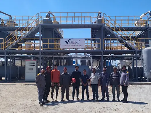
* Temporary demonstration content. Not a verified customer reference.
———— 10 · Engineering Resources
Documents for Technical Evaluation and Project Decisions
Each document has a defined purpose: understand the plant, review the technical basis, follow the process route or provide the information required for engineering selection.
VBOLT · VBT-DD SERIES
Waste Oil to Diesel Plant
TECHNICAL PRODUCT BROCHURE
Technical Product Brochure
A customer-facing overview of the process, plant configuration, equipment modules, reference capacities, utility requirements and project delivery scope.
DATA
TECHNICAL SELECTION
Preliminary Technical Datasheet
Reference operating conditions, capacities, equipment configuration and utility requirements.
PDF · 6 PAGES*
REQUEST PDF →
PFD
PROCESS UNDERSTANDING
Typical Process Flow Diagram
Shows feed preparation, dehydration, selected distillation, catalytic conversion, fractionation, diesel refining and product routing.
PDF · A3*
REQUEST PFD →
FORM
PROJECT EVALUATION
Feedstock & Project Information Form
Collects feed analysis, required capacity, target product, project country and available utilities.
PDF / DOCX*
START EVALUATION→
Need a Project-Specific Process Package?
Submit the feedstock and project basis to receive a configuration prepared for your application.
———— Technical FAQ
Questions Before Project Evaluation
This module will contain product-specific technical and commercial questions after the content stage.
———— 11 · Contact an Engineer
Start With the Project Basis
The final conversion point should ask for engineering information rather than presenting a generic contact form.
01 Feedstock type and available analysis
02 Required processing capacity
03 Target product and intended use
04 Project country and site conditions